Cody Williams
Well-known member
Hey everyone, after a few years of planning, daydreaming, and hemming and hawing over various design ideas I was finally able to start building my first duck boat last month. I needed a boat that would be able to haul myself, dog, gear, and occasionally a buddy comfortably. I also needed a boat that was shallow-water capable and could run a mud motor, as most of the spots I hunt here in Utah aren't accessible with an outboard, but could also run a regular outboard during the summer when fishing from deeper lakes. After looking at several different designs I couldn't shake the lines of the BBIII from my mind, something about that design just says "duckboat" in my mind.
I decided to build her with a few modifications to make shallow water operation easier, namely doing away with the sponsons by relocating the transom to the rear (to make running a surface drive mud motor possible, and also for more cockpit space), reinforcing the transom to handle the extra weight and torque of a mud motor, and the biggest change of all: removing all the rocker from the rear of the boat. My goal with removing the rocker was to make for cleaner water flow to a surface drive prop, allow the boat to plane more easily with a heavy hunting load, and to hopefully decrease the draft a touch by making the boat sit slightly higher in the water. I called Devlin Design and talked to Sam about my ideas, he was fully on board with the transom mod but wasn't so sure about the rocker modification, saying that it would probably work but that I was taking a step into weirdland with regards to the main panel shapes and how the hull would come together. I'm seemingly ever eager to make things harder on myself, so I plunged into the rocker mod full steam ahead. After building a few scale hull models it seemed like I had a pretty good idea of what the hull changes would entail.
Here's the basic hull panels and sides with rear rocker taken out:


The way I did the rocker mod was to add what I removed from the keel line to the tops of the sides, proportionally. This ended up changing the transom width, transom and rear cockpit bulkhead height, side panel length, and side panel height, and overall length by a small margin. After burning countless brain cells and pacing around my shop and garage floor for a few hours I got everything aligned, squared, and shaped properly. Every part of a stitch-and-glue hull really does affect every other part! Had to take the family on a canoe trip to give my brain a bit of a rest!


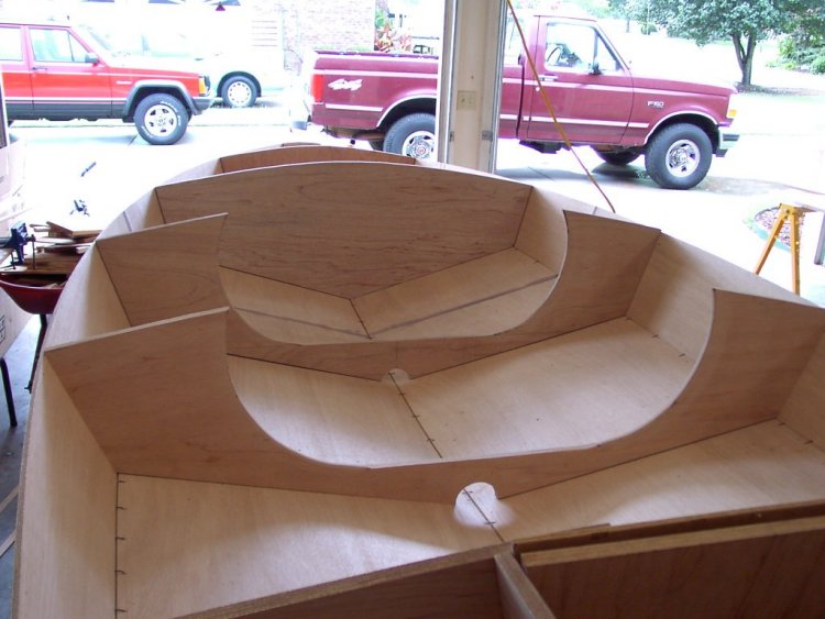
After getting everything squared, leveled, and plumb I was able to start dropping bulkheads in place and finally able to get some epoxy and glass onto okoume!


Ever-loyal shop assistant Sage was a big help, but he keeps getting clumps of epoxy stuck to his fur

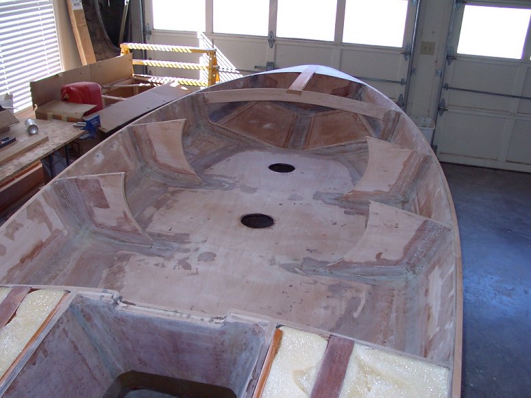
All the time that I was working on the hull I was thinking about the best way to reinforce the transom to handle the extra stress of a mud motor. What I finally came up with was to laminate several pieces together into a thicker transom. I cut the full transom out of 3/4 and in the center section laminated an additional piece of 3/4 plus a layer of 1/4" laminated on top to fit the width of my mud motor mounting bracket. (1 3/4" total thickness in the center section). The outer parts of the transom are laminated with a layer of 3/8 over the 3/4 to add stiffness overall. That leaves a step of about 5/8" between the center section and the outer sections of the transom. My idea here is to use these edges as a landing for some longitudinal bulkheads that will run from the transom to the rear cockpit bulkhead, then be bonded to the bottom of the boat and also form the edges of a splash well. I'm having a hard time explaining what this idea is but maybe some photos will make it clearer:
Reinforced transom

Tacked into place on the boat

Rear cockpit storage space/space for reinforcement "box"

Basically the concept is to form a box with longitudinals between the edges of the rear cockpit bulkhead cutouts and the steps in the transom. I think this will add a lot of strength, and I'm planning to fill the box with pour foam after I install a drain tube and the splash well deck.
That's all I have for now, hopefully I can get some work done the next few nights!
I decided to build her with a few modifications to make shallow water operation easier, namely doing away with the sponsons by relocating the transom to the rear (to make running a surface drive mud motor possible, and also for more cockpit space), reinforcing the transom to handle the extra weight and torque of a mud motor, and the biggest change of all: removing all the rocker from the rear of the boat. My goal with removing the rocker was to make for cleaner water flow to a surface drive prop, allow the boat to plane more easily with a heavy hunting load, and to hopefully decrease the draft a touch by making the boat sit slightly higher in the water. I called Devlin Design and talked to Sam about my ideas, he was fully on board with the transom mod but wasn't so sure about the rocker modification, saying that it would probably work but that I was taking a step into weirdland with regards to the main panel shapes and how the hull would come together. I'm seemingly ever eager to make things harder on myself, so I plunged into the rocker mod full steam ahead. After building a few scale hull models it seemed like I had a pretty good idea of what the hull changes would entail.
Here's the basic hull panels and sides with rear rocker taken out:
The way I did the rocker mod was to add what I removed from the keel line to the tops of the sides, proportionally. This ended up changing the transom width, transom and rear cockpit bulkhead height, side panel length, and side panel height, and overall length by a small margin. After burning countless brain cells and pacing around my shop and garage floor for a few hours I got everything aligned, squared, and shaped properly. Every part of a stitch-and-glue hull really does affect every other part! Had to take the family on a canoe trip to give my brain a bit of a rest!
After getting everything squared, leveled, and plumb I was able to start dropping bulkheads in place and finally able to get some epoxy and glass onto okoume!
Ever-loyal shop assistant Sage was a big help, but he keeps getting clumps of epoxy stuck to his fur
All the time that I was working on the hull I was thinking about the best way to reinforce the transom to handle the extra stress of a mud motor. What I finally came up with was to laminate several pieces together into a thicker transom. I cut the full transom out of 3/4 and in the center section laminated an additional piece of 3/4 plus a layer of 1/4" laminated on top to fit the width of my mud motor mounting bracket. (1 3/4" total thickness in the center section). The outer parts of the transom are laminated with a layer of 3/8 over the 3/4 to add stiffness overall. That leaves a step of about 5/8" between the center section and the outer sections of the transom. My idea here is to use these edges as a landing for some longitudinal bulkheads that will run from the transom to the rear cockpit bulkhead, then be bonded to the bottom of the boat and also form the edges of a splash well. I'm having a hard time explaining what this idea is but maybe some photos will make it clearer:
Reinforced transom
Tacked into place on the boat
Rear cockpit storage space/space for reinforcement "box"
Basically the concept is to form a box with longitudinals between the edges of the rear cockpit bulkhead cutouts and the steps in the transom. I think this will add a lot of strength, and I'm planning to fill the box with pour foam after I install a drain tube and the splash well deck.
That's all I have for now, hopefully I can get some work done the next few nights!
Last edited: